or
First I have to admit I am not the very first to realize this, and even Mr. Yagi who designed the Yagi antenna, fed one with a rectangular loop at times. There is a photo of him doing this on the internet that is a picture of him doing this back in 1965! However when the Cubical Quad Antenna became popular ( when do it yourself antennas ) was in favor, as opposed to let someone else build it (present day), everyone assumed the shape should be square with all sides being the same length. What happens to Yagi's and Quads when you change the shape of the driven element?
This thinking started in the mid 1990's. When computer windows based software programs for modeling became widely available 15-20 years or so ago, the experimentations started to find out.
Some years ago YU7EF presented a new type of Yagi with the "low-noise" principle. That means extreme reduced side lobes for minimizing the receiving of unwanted signals ("noise"). Therefore he changed the travelling wave zone and the end zone of the Yagi. He shortened the directors continuously; the last directors are very short. But there are very low currents in the last directors, which leads to less efficiency and some reduced gain. These Yagi's were long boom 28 Ohm Yagi's. The second YU7EF-principle is the 50-Ohm-direct feed, that means the intrinsic impedance of the Yagi is 50 Ohm. The Yagis can be built with open dipoles or with a 200-Ohm-folded dipole and a half wave balun. This work was also further carried out by in the UHF bands primarily by DK7ZB, YU7XL, DG7YBN, VE7BQH, W4RNL, ON4UN, G4CQM, WA3FET, G0KSC, YT1NT, DJ9BV and a host of others, most of who I forgot their callsigns. So I apologize if I have missed your pioneering efforts. The idea was to try to build low noise antennas, primarily Yagi's. When the idea came up.... why not use a Rectangular folded loop or Quad loop as a Driven element in a Yagi, that should to do 3 things: Make the antenna a lil bit quieter, have slightly more gain and more importantly change the impedance so that it can match 50 Ohm coax directly. The loop as a driven element in the Yagi does all of these things rather well.

I know your first question: Does this give the Yagi the same gain as a Cubical Quad for the same boomlength? NO. But it certainly lets you feed it with straight coax without any transformer baluns to change the impedance. Although some sort of 1:1 common mode current choke 1:1 is still highly recommended. From here the what if's got more interesting.
What if you took the symetrically square Cubical Quad Antenna, and made all of the elements rectangles or Oblong as some prefer to call them. This isn't really rocket science. Although amateur's seeking a commercial market for such an antenna have given them various new names: LFAQ (Loop Fed Array Quad), Oblong's, Rectangles...etc These are really just the same as cubical quads with the elements not being symetrically square (same size on all sides). With any number of names, no matter what you try to call them, there still cubical quads. Way back in the 1960's Bill Orr already was experimenting with different sizes of the sides and even different shapes, he called them all cubical quads. In any case, this fine work by the above mentioned authors has had a few benefits to cubical quads, besides just calling them new names.

It turns out the rectangular shaped cubical quads have more DB Gain! And can also be made to be 50 Ohms, and have great front to back ratio's, wide bandwidth etc.etc. And they can be made out of wire or aluminum! The bigger aluminum rectangular quads are perfect for UHF frequencys because they are small and still very lightweight. This is very important in the ultra competitive world of UHF E-Skip and Tropo communications. Not too mention having low noise figures which no other antenna can compare with.
So is this Quad evolution just for the VHF/UHF bands? No not really, these rectangular shapes can still be made from wire for the HF 10-20 meter bands. Although I have yet to see a rectangular 20 meter full size cubical quad yet! On 10 meters these are certainly do-able, and I have built a few myself, even 5 element all 1/2" aluminum rectangular cubical quads! Although thats about the limit you can do with aluminum on 10 meters without making the antenna and support structure too heavy. But 2 - 4 element aluminum or wire rectangular quads are within easy reach of the antenna experimenter.
OK, tell me about the DB gain difference and what size are we talking about?
Lets start with one element at a time,
isotropic antenna db gain 0
1/4 wave ground plane antenna dbi gain 1
1/2 wave dipole antenna dbi gain 2.15 (yagi driven element)
1 wavelength cubical quad antenna dbi gain 3.4 (cubical quad driven element)
50 ohm fed rectangular shape quad antenna dbi gain 4.3 (doubles a dipole gain)
25 ohm fed rectangular shape quad antenna dbi gain 4.8
Alexander Graham Bell, when he invented the Decibel did not have sophisticated electronic equipment at his disposal, he had his ears! So he decided that 1 decibel, would equal the first noticeable difference in volume between two sounds. Three Decibels would be DOUBLE the volume or signal he heard! So don't listen to "one decibel doesn't matter" it does. If you want to have the difference between hearing someone and not hearing them. Or making contact with that distant dx station and not. Three Decibels is DOUBLE your power! Wouldn't you like to double your power for free?
----------------------------------------------------------------------------------------------------------
How can this be? Why does changing the shape to a rectangle, add more gain?
Well if you read the cubical quad page, I mentioned that cubical quads are often thought of as stacked yagi's in the square shape. Which in essence they are. Lets review that.


Why is this, the picture on the left still looks like a square to me? Well in the picture above on the right the space between both halves of the square happens to be a point where there is zero current flowing, just like if the square was indeed separated into two halves at that point. The point of minimum current is 1/4 wavelength away from the feedpoint, and exactly where the the white spaces are shown above. Lets look at it a bit different. Below

Looking at the Cubical Quad element and the traditional Yagi it is fairly easy to deduce where the current maximum will be. As the current maximum is at the feed point in the center of the two Yagi's, this is also true for the single quad antenna. With the quad is also another current maximum on the opposite side of the loop to the feed point area where the second feed point was in the two stacked Yagi's. They are electrically the same. A cubical quad electrically behaves that same as two stacked yagi's 1/4 wavelength apart. This is fact not some Jibberish designed to confuse you about quads, and make you assume it must be true.
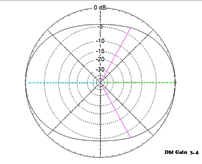
Ok so the cubical quad is just like stacked Yagi's after all (1/4 wavelength apart). Why does it make more gain with a rectangular shape? Well when you make the horizontal or vertical elements longer in a rectangular shape it has effect of squashing the radiation pattern tighter. Lets look at an example to visualize that. The picture below shows a regular square shaped quad above with a side view of the pattern, plus the dbi gain. Below is the rectangular shaped quad pattern. Notice how the two patterns are different? The rectangular shaped quad squeezes more gain out of the pattern.


The pink lines of the photos above represent the 3DB bandwidth, this is the width of the pattern that is within 3 db of one another. In the pictures above the regular square cubical quad has a very wide 3db bandwidth of over 90 degrees. In the photo below you can see that the pattern is now 90 degrees, this mean more signal was focused into this area, hence the higher db gain. These patterns are both for just single loops.
In essence you have made the horizontal portion of the antenna longer for horizontal polarized antennas, and the vertical portion of the antenna shorter. There is less wasted area between the upper and lower halves of the antenna in the horizontal position. Ditto for the Vertically polarized rectangular version. The Vertical portion of the antenna is now longer and the horizontal portion is now shorter. What happens is a reduction in unwanted lobes and putting most of the gain into the main useful lobe is the reason. This is exactly the same reason as to why traditional stacked yagi's have more gain....they squeeze the lobes into the more useful main lobe, this is where the gain increase comes from. It is the same with the standard cubical quad...it is two small stacked yagis, therefore it has more gain than a single yagi, a lower noise pattern (since many side lobes or back lobes are usually minimized), and a slightly lower angle of radiation then a single yagi.
The rectangular version of the standard Cubical Quad makes these antenna characteristics even stronger. Again many competitive 2 meter fans know exactly what I am talking about and have already realized this. Its much easier to build a antenna that is 5X smaller then a 10 meter antenna. So they can do dozens of experiments on different antennas within weeks. The lowest noise / highest gain antennas are always Loop Fed Arrays, whether they be LFA Yagi's or Oblong Cubical Quads.
So how do you know the sizes of the side of the rectangular quad should be? Luckily, this has already been explored and worked out by several smarter than me amateurs. Lets take a square Cubical Quad loop as an example.Horizontal polarization. Like the one shown in the photos above. The standard formula goes like this:
On a standard Cubical Quad Antenna each side is 1/4 or .25 wavelengths long this gives you about 1.2 db gain over a dipole (yagi driven element).
If you make the vertical section of the quad .172 wavelengths long (shorter). And make the horizontal section of the quad .357 wavelengths longer you will have a rectangle that you can feed with 50 coax directly and gain another .9 db over the square quad loop! This for Horizontal polarization.

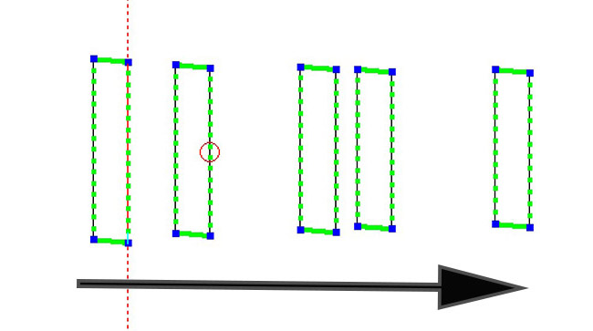
You can also turn the rectangle so that it stands up, and feed it for Vertical polarization (vertical side .357) on the side and get the same results, again with an impedance of 50 ohms. You can create all of the reflectors and directors in your multi element quad the same as the driven element you made. 5% longer in general for the reflectors and 5% shorter for the directors.Those are only approximate sizes.......Until you have something like this:

Whats the pattern look like?

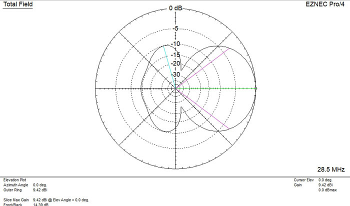
This is 5 element 10 meter oblong quad with only a 24 foot boom, 50 ohms direct feed, and 11.74 dbi gain over a dipole! What would the gain be if this was a well designed normal configuration yagi?

Where did I get this Yagi from? This is the yagi came from the ARRL as an example of a 5 element yagi to use when modeling antennas. Its on the CD thats in the back of the ARRL antenna book when you buy it. 9.42 dbi gain. Certainly a respectable gain figure for a yagi.
It has a 25 foot boom length(1 foot longer than the quad), both are Free Space gain, so height isn't a factor, And its NOT 50 ohms, you would need to use some type of matching unit to make it 50 ! Besides just the db gain difference and having to match it, which do you think would make a quieter antenna? Look at the two patterns. It's not even close. The oblong cubical quad in this case annihilates the 5 element yagi.
As I mentioned, these oblong cubical quads can be made out of Wire or Aluminum (like yagi's). The Fatter aluminum tubes will give you slightly more gain and bandwidth BUT... The element size of the aluminum, let's say 1/2" tubing WILL change the SWR (from typical #12 gauge wire). So you will have to experiment quite a bit to get a direct 50 ohm feed. Unless... you have Eznec software, then you can change sizes and thickness of your elements in your house first on your computer. Then have a close to real life SWR expectation when you actually build the Quad. I HIGHLY recommend you learn some kind of Antenna Software. Its critical if you want to learn about antennas especially if your a builder of the antenna yourself.
-----------------------------------------------------------------------------------------------------------------------------------
What if you wanted to get more gain? Horizontal polarization: Make the vertical side only .14 wavelengths long and the horizontal side .42 wavelengths long. Vertical polarization: Make the vertical side .42 wavelengths long and the horizontal side .14 wavelengths long. Now you have added .5 db gain, BUT you also have a oblong quad that is only 25 ohms. So you would have to match it with a balun 25-50 ohms or some other kind of matching device. Since these matching devices and baluns do have some loss, the db gain that is extra would probably be mostly eaten up by the matching unit. So I'll pass on this, although I know there is a amateur radio crowd that doesn't believe in matching loss, so for you...knock yourself out.
Does this mean, that all cubical quads will change shape into rectangles in the future? Probably not, and even if they do I am sure they will be labeled with another name. There is already a couple of manufacturers making these antennas in Europe. Where people tend to be a bit more DIY (do it yourself) oriented.

But for those of you who want to build the highest gain , lowest noise, best performance single antenna you can have. This is it.
The Ultimate test of an Ham Radio Antenna, is not whether they can hear you, but whether you can hear them.
With a Cubical Quad Antenna, you will most likely be able to hear them better then any other HF Antenna.
Last Updated: